
Why Do Safety Relays Fail? Common Causes
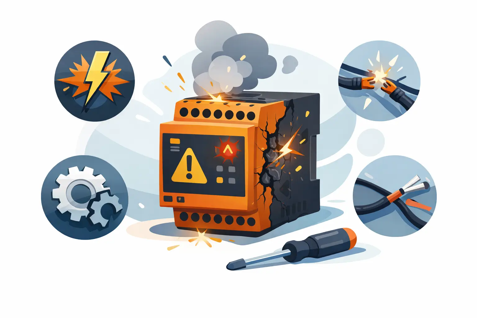
A safety relay that will not reset can stop a production cell as completely as a failed drive or PLC output. The difference is that bypassing the problem is not an acceptable repair. When teams ask, why do safety relays fail, the answer is usually not a single defective component. It is often a wiring fault, failed field device, power-quality issue, configuration error, or damaged output circuit that the relay is correctly detecting.
Safety relays monitor safety devices such as emergency stops, guard switches, light curtains, two-hand controls, and safety mats. They verify that input channels change state as expected and that output contacts can safely remove power from hazardous motion. A relay that remains locked out may be preventing an unsafe restart. Troubleshooting must therefore start with the machine's safety documentation, the relay wiring diagram, and established lockout/tagout procedures.
Why Do Safety Relays Fail in Industrial Equipment?
Safety relays operate in demanding conditions: frequent cycling, inductive loads, electrical noise, temperature changes, vibration, and contamination. A failure can be internal, but the symptoms can look identical to a problem elsewhere in the safety circuit.
The first task is to separate a relay fault from a valid safety trip. Check the relay's status LEDs, diagnostic codes, input channel condition, reset circuit, and output feedback loop. Compare the observed state to the manufacturer documentation for that exact part number. Siemens, Omron, Allen-Bradley, Schneider Electric, ABB, and other manufacturers use different terminal assignments, reset logic, and diagnostic indicators. Do not assume one relay's behavior applies to another.
Worn or Damaged Safety Output Contacts
Electromechanical safety relays use force-guided contacts. Their design helps detect welded contacts, but it does not make them immune to wear. Output contacts can deteriorate after repeated switching, especially when they control contactor coils, solenoids, brakes, or loads with high inrush current.
A contactor coil without adequate surge suppression can create a voltage transient every time it is de-energized. Over time, this can erode relay contacts and shorten service life. Oversized loads, incorrect fuse selection, and switching a load beyond the relay's rated category can produce the same result.
A welded or mechanically damaged contact may prevent the relay from resetting because its internal monitoring circuit detects that the contacts did not return to their required state. In this situation, replacing only the relay without checking the downstream load and suppression method can lead to an early repeat failure.
Failed External Contactors and Feedback Circuits
Many safety circuits use external contactors to remove power from motors, valves, or machine actuators. The safety relay monitors auxiliary contacts on these devices through an external device monitoring, or EDM, loop. If a contactor welds, sticks, has a failed auxiliary contact, or is wired incorrectly, the feedback circuit remains open and the safety relay will not reset.
This is one of the most common sources of misdiagnosis. The relay may appear failed because its outputs do not energize, but it is correctly blocking restart after detecting that a contactor did not drop out. Inspect contactor condition, auxiliary contact operation, coil voltage, and EDM wiring before condemning the relay.
Input Device and Dual-Channel Wiring Problems
Safety relays expect defined behavior from each input channel. An emergency-stop contact with oxidation, a misaligned guard switch, a damaged light curtain cable, or a loose terminal can interrupt one channel. On a dual-channel circuit, a timing mismatch or cross fault can also prevent reset.
Common field issues include broken conductors at moving guard doors, pinched cables in machine frames, incorrect jumper placement, and terminals that loosen from vibration. Moisture and washdown exposure can accelerate corrosion at field devices and junction points. A continuity test alone may not find an intermittent fault, so inspect wiring while moving the cable and operating the guard or E-stop device.
When replacing an input device, confirm its contact arrangement and switching characteristics. A normally closed mechanical E-stop, coded non-contact guard switch, and OSSD safety sensor do not connect to every safety relay in the same way. Compatibility matters as much as terminal fit.
Power Quality and Control Voltage Issues
Safety relays require a stable supply voltage. A brief control-power dip may cause the relay to drop out, even if the PLC remains energized. This can happen when a large motor starts, a power supply is undersized, a shared DC circuit is overloaded, or loose supply terminals create voltage drop under load.
Measure voltage at the relay terminals during the event, not only at the power supply. Check for excessive ripple on DC supplies, blown or marginal fuses, poor grounding, and shared circuits that introduce noise from variable frequency drives or high-current switching devices.
Incorrect voltage is also a frequent replacement error. A 24 VDC safety relay and a 120 VAC version may look similar in a panel, but they are not interchangeable. Verify the catalog number, supply specification, output rating, reset mode, and terminal layout against the machine documentation before ordering a replacement.
Reset Circuit Errors
A manual reset circuit must be wired and operated according to the relay's intended logic. Some relays require a monitored falling edge, while others expect a momentary rising-edge signal. A reset button that is stuck, wired as a maintained contact, or connected to the wrong terminal may keep the relay from starting.
Automatic reset can be appropriate only where a risk assessment permits it. For guarded machinery or applications where a person could remain in a hazardous area, manual monitored reset is often required. Changing reset mode to get a machine running can create a safety and compliance problem rather than a repair.
Environmental Stress and Installation Conditions
Heat is a major contributor to relay aging. A safety relay installed beside a VFD, power supply, transformer, or heavily loaded contactor may operate above its rated ambient temperature. High enclosure temperature accelerates insulation degradation and can affect electronic components within configurable or solid-state safety relays.
Vibration can loosen terminals and damage mechanical assemblies. Dust, conductive debris, oil mist, corrosive chemicals, and washdown exposure can affect both the relay and connected field wiring. Check enclosure ratings, panel ventilation, rail mounting, conductor strain relief, and the spacing recommendations for the specific relay family.
For facilities with recurring failures, record the relay location, ambient conditions, load type, cycle count, and fault symptoms. A pattern across the same machine area usually points to an application problem, not a random series of bad parts.
Age, Lifecycle, and Incorrect Replacement Parts
Safety components have electrical and mechanical life limits. A relay used for frequent machine cycling may reach its practical service life sooner than one used only for occasional E-stop functions. Lifecycle depends on load current, switching frequency, environmental conditions, and whether external contactors carry the main load.
Legacy systems create another challenge. An obsolete relay may be replaced with a newer model that has similar inputs and outputs but different timing, feedback monitoring, or reset requirements. The machine may then fail validation or remain in a faulted state. A replacement must be evaluated for functional equivalence, not selected solely by voltage or contact count.
For a critical repair, document the original manufacturer and full catalog number, including suffixes. Confirm whether the installation uses expansion modules, timing modules, safety contactors, or compatible sensors that affect the replacement choice. Maintaining accurate panel records reduces downtime when the next failure occurs.
A Safe Troubleshooting Sequence
Start by securing the machine under site lockout/tagout requirements. Then review relay indicators and diagnostics, verify supply voltage at the relay, and inspect every safety input for the expected channel state. Check the reset circuit and the feedback loop from external contactors before testing output behavior.
If the relay indicates an internal fault, or if testing confirms contacts cannot change state correctly, replace it with the correct approved part and validate the complete safety function before returning the machine to service. Do not jump safety terminals, force contactors closed, or permanently bypass a field device to restore production.
A failed safety relay is a maintenance event, but it is also useful evidence. The failed component, wiring condition, contactor status, and operating environment can show where the safety circuit needs attention. Purchasing the right replacement part quickly matters, but finding the condition that caused the failure is what protects uptime on the next shift.