
What Is a Safety Relay? Functions and Selection
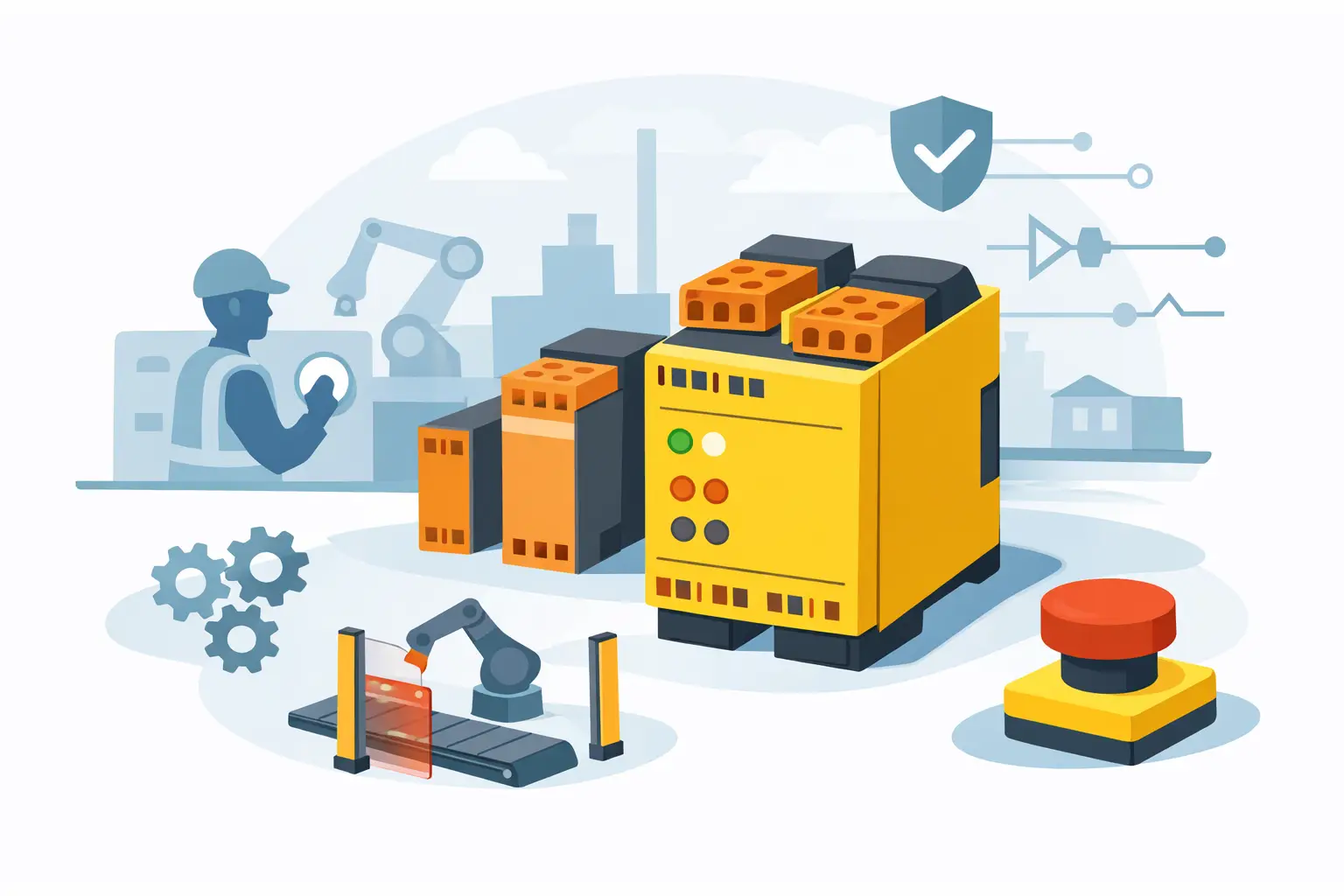
A machine stop circuit that removes power only when a wire breaks is not necessarily a safety circuit. It may stop the machine under one fault condition while leaving other failures undetected. That distinction answers the practical question, what is a safety relay: it is a purpose-built control device that monitors safety inputs and uses internally monitored output paths to place machinery into a defined safe state when a hazard, wiring fault, or component failure is detected.
Safety relays are common in packaging lines, conveyors, presses, robotic cells, material handling equipment, and OEM machinery. They are used with devices such as emergency-stop pushbuttons, safety gates, interlock switches, light curtains, safety mats, and two-hand controls. For maintenance and controls teams, the relay is the part of the system that turns a safety-device signal into a verified command to remove hazardous motion or energy.
What Is a Safety Relay?
A standard control relay changes the state of its contacts when its coil is energized or de-energized. It may be suitable for normal machine logic, but it is not designed to detect every dangerous internal or external fault. A safety relay adds fault-monitoring architecture, usually including redundant internal relays or electronic channels, positively guided contacts, and feedback monitoring.
When a safety input is in its normal, permitted state, the safety relay can energize its safety outputs. Those outputs are typically wired to contactors, motor starters, safety-rated drives, pneumatic dump valves, or other final switching devices. When an emergency stop is pressed, a guard opens, or the relay detects an invalid condition, the safety outputs de-energize. The controlled equipment then transitions to its designed safe state.
The safe state depends on the application. On many machines, it means removing power to a motor through redundant contactors. In another application, it may mean applying a brake, venting pneumatic pressure, stopping a drive through a safety input, or preventing a restart after a guard is opened.
A safety relay does not make a machine safe by itself. It is one component in a safety function that also includes the input device, wiring, final switching elements, mechanical stopping performance, risk assessment, and validation.
How a Safety Relay Detects Faults
The difference between a safety relay and an ordinary relay is not simply that it has more contacts. The value is in the way the circuit is supervised.
Most safety relays use dual-channel inputs for safety devices. For example, an emergency-stop device with two normally closed contacts can be connected to two input channels. The relay expects both channels to change state within a defined time relationship. If one contact is welded, one wire is shorted, or the two channels do not agree, the relay can prevent reset or drop out its outputs.
Many units also provide short-circuit or cross-fault detection. This helps identify faults between channels that could otherwise defeat a two-channel input design. The available detection method depends on the relay model and wiring arrangement, so the product manual matters. Some devices use test pulses, and certain field wiring practices or connected devices can affect compatibility.
Feedback Monitoring of Final Switching Devices
A safety relay may include an external device monitoring, or EDM, circuit. This circuit checks the auxiliary contacts of downstream contactors or relays before allowing a reset.
Consider a motor controlled by two contactors. If one contactor welds closed, the safety relay may command both contactors off but the motor circuit could remain energized through the failed contactor. With correctly wired feedback contacts, the safety relay sees that the contactor did not return to its off position and blocks the next reset. This does not repair the failure, but it prevents an unnoticed restart.
Manual and Automatic Reset
Reset behavior is a key selection and wiring decision. A manual monitored reset requires a deliberate action, normally from a reset pushbutton located where the operator can observe the hazard area. This is common after an emergency stop or guard opening because it prevents an automatic restart when the safety device returns to normal.
Automatic reset can be appropriate when a risk assessment permits it and no person can be exposed to an unexpected restart. It should not be treated as a convenience setting. The reset method must match the machine's safeguarding concept and applicable requirements.
Safety Relay Inputs and Outputs
A typical safety relay has safety inputs, safety outputs, auxiliary outputs, and reset or feedback terminals. Terminal names vary by manufacturer, so exact wiring must follow the device documentation and the approved machine design.
Safety inputs receive signals from devices such as E-stops, guard switches, light curtains, or safety sensors. Safety outputs are often normally open contacts designed to energize control circuits only when the safety function is healthy. Auxiliary contacts may report relay status to a PLC, HMI, stack light, or diagnostic circuit, but they should not be assumed to be safety-rated outputs unless the manufacturer specifically identifies them that way.
Output ratings require careful review. A relay may have force-guided contacts suitable for monitoring, but its contacts may not be sized to switch a large motor load directly. In many panels, the safety relay controls interposing contactors or a drive's safety input rather than carrying the motor current itself. Check the AC or DC voltage, current, utilization category, inductive-load rating, and required suppression for the actual load.
Safety Relay vs. Safety PLC
A safety relay is usually the right fit for a simple, fixed safety function. A single emergency-stop zone, one access gate, or a small light-curtain circuit can often be implemented with a compact relay and clearly documented hardwired logic. This approach is direct, familiar to troubleshooting personnel, and can reduce engineering effort on straightforward machines.
A safety PLC is often a better fit where there are multiple zones, muting logic, several interlocked gates, mode selection, distributed I/O, detailed diagnostics, or frequent design changes. It can consolidate complex safety logic, but it also requires appropriate programming, validation, access control, and lifecycle management.
The choice is not a matter of one technology being universally better. For a simple press guard circuit, a dedicated safety relay may be easier to troubleshoot and replace. For a conveyor system with many zones and coordinated stops, a configurable safety controller may provide better visibility and reduce panel complexity.
How to Select a Safety Relay for a Replacement or New Build
Start with the existing part number when replacing a failed unit. A relay that looks similar may differ in supply voltage, input type, reset logic, output configuration, timing, terminal layout, or safety capability. Cross-referencing should verify the complete application requirement, not only the footprint.
For a new design or an engineered replacement, identify the safety function first. Determine what initiates the stop, what must be de-energized, how the machine reaches a safe condition, and whether feedback from contactors or valves is required. Then confirm the required performance level or safety integrity target through the machine risk assessment and relevant standards.
Review these specifications before ordering:
- Supply voltage and permissible voltage range, such as 24 VDC or 120 VAC
- Input compatibility with the connected safety device, including dual-channel wiring and test-pulse behavior
- Number and type of safety outputs, plus auxiliary diagnostic contacts
- Output load ratings and the interface required for contactors, drives, valves, or other final elements
- Reset method, EDM capability, timing functions, and required restart prevention
- Mounting dimensions, terminal style, environmental rating, and available panel space
Brand and product family consistency can also matter. Plants often standardize on manufacturers such as Siemens, Schneider Electric, Omron, ABB, Allen-Bradley, or Phoenix Contact to simplify spares, documentation, and technician familiarity. Standardization is useful, but it does not remove the need to confirm the exact model, revision, and wiring requirements.
Installation and Troubleshooting Considerations
A safety relay should be installed by qualified personnel using the manufacturer's instructions and the machine's approved safety design. Keep safety wiring identifiable, use appropriate conductor protection, and separate circuits where required to reduce the risk of unintended faults. Do not bypass a safety input to keep production moving. A bypass can create a hazardous condition and obscure the original failure.
When a relay will not reset, begin with the input chain. Verify that emergency stops are released, guards are closed, and both channels change state as expected. Next, inspect the reset circuit and the feedback loop from downstream contactors. A welded contactor, damaged actuator, open wire, incorrect jumper, or mismatched input device can all prevent reset.
LED indicators can speed diagnosis, but they are not a substitute for measured verification. Check the wiring diagram for the exact relay model, confirm supply voltage at the terminals, and test the state of each field device. If a replacement is needed, record the full catalog number and any expansion modules or timing accessories before placing the order.
A correctly selected safety relay supports a machine's safety function and helps prevent a known fault from becoming an unexpected restart. For procurement, the practical priority is accuracy: match the part number, verify the application details, and ensure the replacement fits the complete safety circuit rather than only the DIN-rail space.