
Choosing a Replacement Contactor for Motor Starter
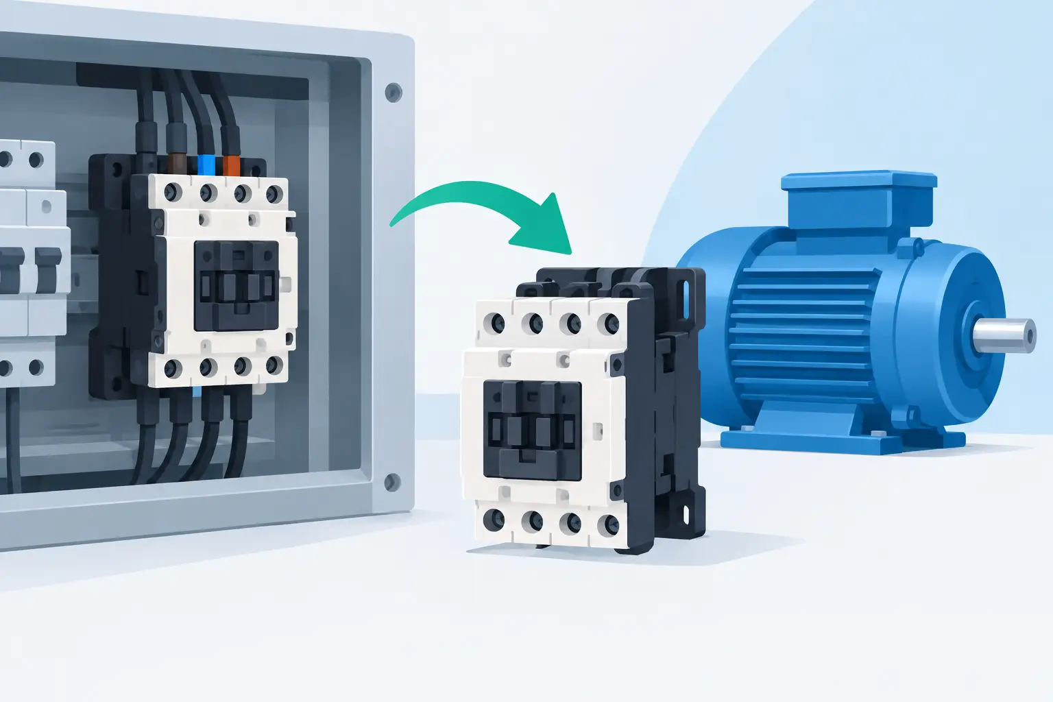
A failed contactor can stop a conveyor, pump, fan, compressor, or production cell without warning. Ordering a replacement contactor for motor starter equipment is not simply a matter of matching the amp rating on the old device. The new contactor must fit the electrical duty, control circuit, overload arrangement, enclosure space, and operating requirements of the existing starter.
For maintenance teams and buyers, the fastest path is to identify the original manufacturer and exact catalog number first. When that number is unavailable, damaged, or obsolete, a structured comparison of the starter components can prevent an incorrect purchase and avoid another shutdown after installation.
Start With the Existing Part Number
The original contactor catalog number is the strongest reference for a direct replacement. It identifies the product family, pole configuration, coil voltage, current class, auxiliary-contact arrangement, and often the compatible overload relay series. A clear photo of the front label, side label, and terminal markings can help confirm the part when documentation is incomplete.
Record the manufacturer, full part number, coil designation, and any suffixes. A contactor that appears identical from the front may have a different AC or DC coil, a different number of built-in auxiliary contacts, or terminals that do not match the existing wiring method. Those differences matter in a motor starter circuit.
If the existing contactor is part of a modular starter, identify the overload relay separately. Many motor starter assemblies use a contactor and overload relay designed to mount together. A replacement contactor may be electrically capable but mechanically incompatible with the existing overload block.
Match the Electrical Rating to the Motor Duty
Contactor selection begins with the motor load, not just the branch-circuit protection rating. Review the motor nameplate for voltage, phase, full-load current, horsepower, and frequency. Then compare those values with the contactor's published motor-duty ratings at the application voltage.
A contactor's ampere rating can be stated differently depending on its utilization category. For a typical squirrel-cage induction motor started and stopped under normal conditions, AC-3 duty is commonly the relevant reference. Applications involving plugging, jogging, inching, reversing, or frequent starts may require a different duty rating. A contactor that is acceptable for standard running duty can wear prematurely if used for repeated high-stress switching.
Do not size the replacement solely by frame size or by the current stamped on a competitor's part. Manufacturers may use different rating conventions and test conditions. The correct cross-reference must support the motor's voltage, horsepower, switching duty, and expected operating cycle.
Consider application conditions
Ambient temperature, enclosure heat, altitude, and switching frequency can affect performance. A contactor installed in a tightly packed panel near drives, transformers, or other heat-producing equipment may need additional consideration. High-cycle equipment such as packaging machinery, automatic doors, pump controls, and repetitive indexing systems can also place more demand on the contact set than a lightly used motor circuit.
For reversing starters, use contactors intended for mechanically and electrically interlocked operation. Replacing only one side of a reversing pair with a mismatched unit can create mounting, interlock, and control-circuit problems.
Verify Coil Voltage and Control Circuit Type
A correct power contactor will still fail to operate if the coil is wrong. Read the coil marking directly from the existing device and verify whether the control circuit uses AC or DC voltage. Common control voltages include 24 VAC, 24 VDC, 120 VAC, 208-240 VAC, and 480 VAC, but the actual coil requirement must be confirmed at the equipment.
Do not assume the coil matches the motor supply voltage. A 480 V motor starter may use a 120 V control transformer, while a newer control panel may use 24 VDC from a power supply. Installing the wrong coil can cause an immediate failure to pull in, coil burnout, or damage to the control circuit.
Also check whether the original has an electronic coil or an economy coil. Some modern contactors have lower holding consumption, wider voltage tolerance, or built-in suppression characteristics. These can be useful features, but they should not be treated as automatic substitutes when the control system has sensitive outputs, interface relays, or PLC-controlled circuits.
Check Poles, Auxiliary Contacts, and Terminal Layout
Most across-the-line three-phase motor starters use a three-pole contactor, but the complete control circuit often depends on auxiliary contacts. A normally open auxiliary contact may provide a seal-in circuit, run indication, or PLC input. A normally closed contact may support an interlock, fault circuit, or permissive condition.
Count the auxiliary contacts on the existing contactor and identify their normal state. Check whether they are built in, front-mounted, side-mounted, or supplied through an auxiliary contact block. The replacement must provide the required contact logic and have sufficient current and voltage capability for the control circuit.
Terminal layout deserves the same attention. Verify line and load terminal positions, wire range, lug style, control terminal numbering, and panel clearance. A replacement with a different physical footprint may require new wires, different terminal accessories, or modifications to the DIN rail and enclosure layout. That can be acceptable during a planned upgrade, but it is not ideal when restoring production quickly.
Confirm Overload Relay Compatibility
The overload relay protects the motor from sustained overload conditions. In many starters, it attaches directly to the bottom of the contactor and receives power through a specific mechanical interface. This is why a replacement contactor for motor starter service should be evaluated as part of the complete assembly.
If the overload relay remains in service, confirm that the replacement contactor accepts that exact relay family and mounting system. Verify the overload adjustment range against the motor full-load current and check the reset mode, trip class, and auxiliary trip contacts used by the control circuit.
When the existing overload is damaged, obsolete, or no longer compatible, replacing the contactor and overload relay as a matched set is often the more dependable choice. It may add cost compared with changing one component, but it reduces uncertainty around fit, trip behavior, and wiring changes.
Direct Replacement or Cross-Brand Alternative?
A same-manufacturer, same-part-number replacement usually offers the lowest installation risk. It preserves mounting dimensions, wiring locations, accessory compatibility, and documentation continuity. For a critical machine with little downtime available, that is often the preferred procurement decision.
A cross-brand replacement can be appropriate when the original part is discontinued, unavailable, or part of a broader panel modernization. However, it should be treated as an engineered substitution rather than a visual match. Compare electrical ratings, coil characteristics, auxiliary-contact requirements, overload interface, SCCR implications, enclosure space, and applicable code requirements.
For listed industrial control panels, changes can affect the original panel evaluation and field compliance requirements. Plant engineering or a qualified controls professional should review substitutions where certification, machine safety, or documented specifications are involved.
Build a Better Replacement Request
A complete request reduces back-and-forth and improves the chance of receiving the correct part on the first order. Include the original contactor manufacturer and catalog number, photos of all labels, coil voltage, motor nameplate details, overload relay number, and a description of the application. Mention whether the equipment uses reversing, jogging, high-cycle operation, PLC outputs, or safety interlocks.
For facilities supporting multiple equipment brands, keeping this information in the maintenance record is worthwhile. A short list of approved contactor and overload relay combinations can speed future repairs, support stocking decisions, and limit last-minute substitutions.
American Automation 24 supports part-number-based sourcing across major industrial automation brands, which can help buyers compare direct replacements and compatible options when a motor starter component needs to be identified quickly.
Before energizing any replacement, have qualified personnel inspect torque values, conductor terminations, overload settings, control wiring, interlocks, and rotation where applicable. The right contactor is the one that restores the starter's intended electrical and mechanical function without creating a new point of failure.