
How to Wire Control Transformers in Panels
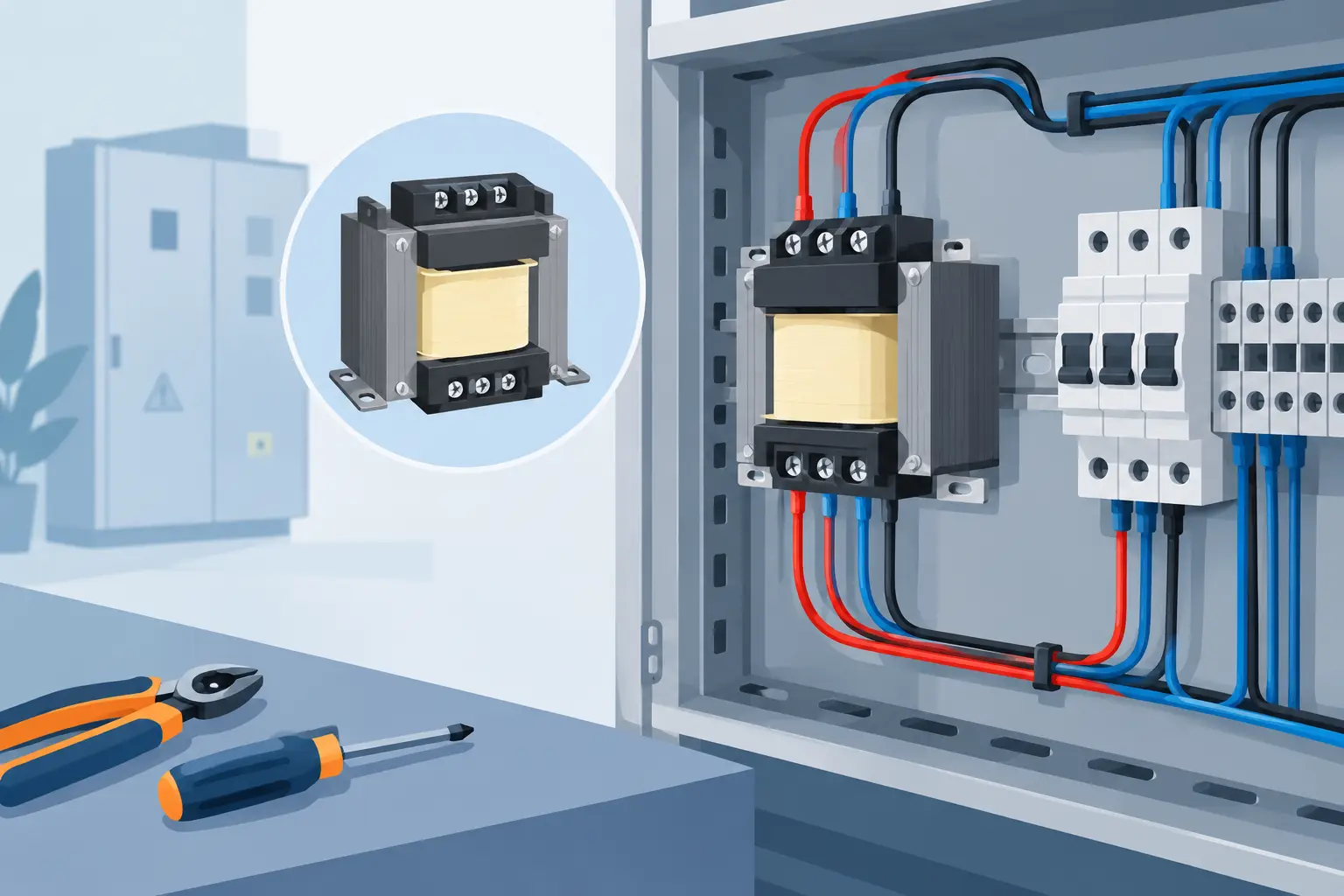
A control transformer can be physically small and still be the source of a costly panel failure. A wrong primary tap, an unprotected secondary conductor, or a grounded circuit where an ungrounded control system was intended can create nuisance trips, damaged components, or unsafe troubleshooting conditions. Knowing how to wire control transformers starts with reading the exact transformer diagram and designing the circuit around the available supply, required control voltage, load, and applicable code requirements.
This guidance is intended for qualified electrical and controls personnel working on industrial control panels. Always de-energize, lock out and tag out equipment, verify absence of voltage with properly rated test equipment, and follow the transformer manufacturer’s instructions, NEC requirements, local codes, and site standards.
Start With the Transformer Nameplate and Schematic
Do not assume terminal labels are universal. Many industrial control transformers use H terminals for the primary winding and X terminals for the secondary winding, such as H1 and H2 on the primary and X1 and X2 on the secondary. Multi-tap models may add terminals such as H3 or H4 to support 208 V, 230 V, 460 V, or 480 V supply options. A dual-secondary model may provide X1 through X4 for series or parallel connection.
The nameplate and wiring diagram determine the correct connections. Confirm the primary voltage available at the panel, the required secondary voltage, frequency, VA rating, insulation class, and terminal arrangement before selecting a tap or landing conductors. A 480 V primary connection made to a 240 V tap can destroy a transformer immediately. Connecting a 24 V control circuit to a 120 V secondary creates the same kind of problem downstream.
Check whether the transformer is intended for 50/60 Hz service. A transformer rated only for 60 Hz should not be assumed suitable for a 50 Hz application at the same voltage. Frequency affects magnetic flux and overheating risk.
Size the Control Transformer Before Wiring It
Transformer VA capacity must support the real control load, not just the normal running current. Add the VA requirements of contactor coils, relays, solenoid valves, pilot lights, timers, PLC power supplies, interface modules, and other loads connected to the secondary. For AC loads, VA is generally calculated as volts multiplied by amps.
The difficult part is inrush. A contactor or solenoid may have a substantially higher pickup VA than its sealed, or holding, VA. If several devices can energize simultaneously, their combined inrush may pull secondary voltage low enough to chatter contactors or reset control electronics. This is especially common when a machine starts multiple motor starters, valve banks, or safety relays at once.
Allow reasonable capacity above the calculated load. The correct margin depends on the application. A simple relay panel may need little additional capacity, while a panel with frequent simultaneous coil pickup, long control runs, or future expansion should have more headroom. Oversizing also has trade-offs: it can increase available fault current and may require a different protection strategy.
How to Wire Control Transformers on the Primary Side
Feed the transformer primary from a properly selected disconnect, circuit breaker, or fused branch circuit. The primary conductors and overcurrent protective device must be selected according to the transformer instructions and the governing electrical code. Control transformer primary fusing is commonly used to protect the transformer and associated conductors, but the appropriate fuse class, ampere rating, and interrupting rating depend on the installation.
With the supply verified de-energized, connect the incoming conductors to the exact primary terminals shown for the measured supply voltage. For example, a transformer with 240 V and 480 V taps will show a specific H-terminal arrangement for each supply. Never bridge or cap terminals based on a terminal-label assumption alone.
Keep the primary wiring separated from low-voltage secondary wiring where practical. Route conductors cleanly, protect them from sharp edges, use wire sizes and insulation ratings suitable for the circuit, and torque all terminals to the manufacturer’s published value. Loose transformer terminations generate heat and can produce intermittent control faults that are difficult to locate.
If the transformer has electrostatic shielding, connect the shield terminal as specified by the manufacturer. A shield is not the same as a grounded secondary conductor. Its purpose is typically to reduce the transfer of electrical noise from the primary to the secondary.
Wire and Protect the Secondary Circuit Correctly
Connect the required secondary voltage from the designated X terminals to the control circuit. For a standard 120 V secondary, X1 and X2 may feed the control power rails. For a 24 V secondary, those same labels may feed 24 VAC loads. The voltage is determined by the transformer design and connection diagram, not by the terminal letters themselves.
Install secondary overcurrent protection close to the transformer secondary terminals when required by the design and applicable code. Secondary fuses or miniature circuit breakers limit damage if a control wire or component faults downstream. They also make it easier to isolate a failed branch without taking down an entire machine.
A common arrangement uses a fused hot leg for a grounded 120 V control circuit, with the other secondary leg bonded to ground at one designated point. That approach is not universal. Some systems use an ungrounded secondary to support insulation monitoring or to reduce certain ground-fault shutdown issues. Other systems may require a grounded circuit for personnel safety, code compliance, or machine standardization.
The key rule is to make the grounding decision intentionally. If the secondary is grounded, bond one conductor at one point only. Multiple neutral-to-ground bonds can create parallel return paths and confusing troubleshooting readings. If the secondary remains ungrounded, label it appropriately and ensure the maintenance team understands the fault-detection method used in the panel.
Series and Parallel Secondary Windings Require Care
Some control transformers have two identical secondary windings. These can often be wired in series to increase voltage or in parallel to increase current capacity at the same voltage. For example, two 12 V secondaries may provide 24 V in series or 12 V at a higher VA capacity in parallel.
Series and parallel connections are only valid when the manufacturer’s diagram permits them. Winding polarity matters. A reversed parallel connection can effectively create a shorted winding condition, while an incorrect series connection can cancel voltage rather than add it. Verify terminal designations, jumper placement, and final output voltage before connecting sensitive controls.
Do not parallel secondaries from different transformers unless the equipment manufacturer and a qualified engineer have specifically designed the arrangement. Even nominally identical transformers can have differences that cause circulating current and overheating.
Check Voltage Drop, Noise, and DC Power Supply Inputs
Long secondary runs can create voltage drop, especially with 24 VAC circuits carrying solenoid or contactor loads. A transformer may measure the correct voltage at its terminals while a device at the far end of the machine sees too little voltage to pull in reliably. Measure voltage under load at both locations when troubleshooting.
Control transformers feeding AC-to-DC power supplies need similar attention. A 24 VAC transformer does not directly replace a regulated 24 VDC power supply. The power supply input range, inrush current, and VA demand must be compatible with the transformer output. For PLCs, sensors, communication devices, and electronic safety equipment, a properly rated industrial DC power supply is often the more appropriate source.
Keep transformer secondary conductors away from high-current motor leads and variable frequency drive output wiring when panel layout allows. Use appropriate shielding and grounding practices for analog, encoder, and communication circuits. A control transformer will not correct poor wiring segregation or improper cable termination.
Test the Installation Before Connecting the Full Load
Before energizing the primary, inspect the panel for correct tap selection, terminal torque, conductor identification, fuse installation, bonding, and wire routing. Verify that unused leads are individually insulated and secured. Confirm that secondary protection matches the approved schematic.
Energize with the secondary load isolated when the design permits. Measure primary voltage at the transformer input and secondary voltage at the X terminals. Compare measured values with the expected nameplate output. Then connect or enable loads in stages while watching for abnormal voltage sag, heat, noise, fuse operation, or coil chatter.
Document the transformer part number, primary tap, secondary voltage, protective device ratings, and control circuit grounding method in the panel drawings. That record matters when a maintenance team needs an exact replacement after a failure. For multi-brand MRO requirements, American Automation 24 can help buyers identify compatible control transformer and protection components by manufacturer and part number.
A properly wired control transformer should disappear into normal operation: correct voltage at the load, protected conductors, clear labeling, and no unexplained resets. Taking the extra time to verify taps, VA demand, and secondary protection is usually far less expensive than diagnosing a machine that will not stay online.