
How to Size Pneumatic Cylinders Correctly
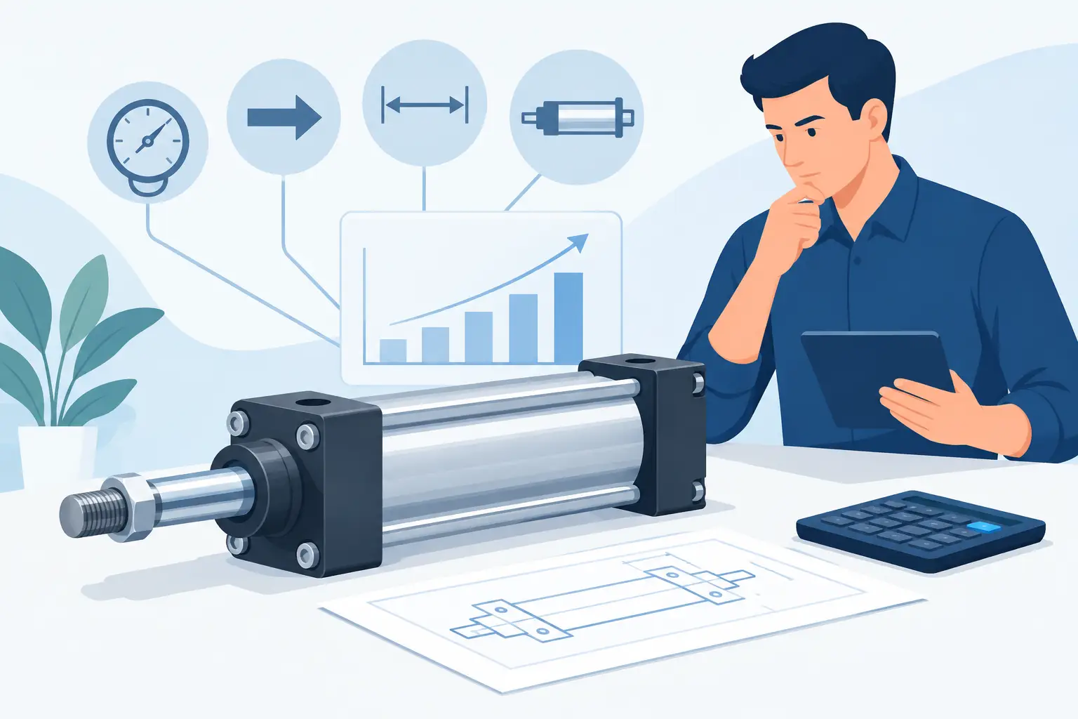
A pneumatic cylinder that is undersized may move a load during a dry run and then stall when product weight, friction, or supply pressure changes. An oversized unit can waste compressed air, increase cycle impact, and create unnecessary mounting and space issues. To size pneumatic cylinders correctly, start with the actual load case at the machine, not the bore size of the cylinder being replaced.
For maintenance and engineering teams, the correct selection comes down to force at available pressure, required stroke, cycle speed, mounting geometry, and the way the load is guided. These values also determine the replacement part details that must match: bore, rod diameter, stroke length, port size, mounting style, sensor capability, and manufacturer series.
Start With Required Force
Cylinder force is produced by air pressure acting on piston area. For an extending cylinder, the basic calculation is:
Force (lb) = Pressure (psi) x Piston area (in²)
Piston area is calculated as π x bore² / 4. A 2-inch bore cylinder has an area of about 3.14 square inches. At 80 psi, its theoretical extension force is approximately 251 lb.
That number is only a starting point. The cylinder must overcome the load, seal friction, guide friction, tooling resistance, and any force required to accelerate the mass. If the cylinder operates vertically, include the full weight of the moving assembly. For inclined motion, calculate the relevant component of gravity rather than assuming the full load weight.
Use a practical force margin rather than sizing exactly to the calculated requirement. A margin of 25% is common for stable, well-understood applications. Higher margins may be appropriate where friction changes, supply pressure fluctuates, product loads vary, or motion includes shock. Excessive margin has a cost, though: a much larger bore consumes more air and can drive the mechanism too hard.
Account for Retraction Force
Retraction force is lower than extension force on a standard double-acting rod cylinder because air acts on the piston area minus the rod area. This distinction matters when the cylinder pulls a load, retracts a spring-loaded mechanism, or must break free from a sticking position.
The calculation is:
Retraction force (lb) = Pressure (psi) x (piston area - rod area)
Do not assume a cylinder that has adequate push force also has adequate pull force. Check the direction that represents the worst operating condition.
Verify Available Air Pressure at the Cylinder
System compressor pressure is not necessarily cylinder pressure. A plant may maintain a 100 psi header, while a regulator is set to 70 psi and pressure drops further during a high-demand portion of the cycle. Long undersized tubing, restrictive fittings, dirty filters, and valve flow limits can all reduce pressure at the cylinder.
Size pneumatic cylinders using the minimum pressure expected at the cylinder inlet during operation. For a machine that must run at 70 psi but occasionally falls to 60 psi, use 60 psi in the force calculation unless the air system issue will be corrected. This approach avoids selecting a cylinder that works only under ideal conditions.
For replacements, confirm the regulator setting, valve specification, tubing outside diameter, fitting type, and port thread before ordering. A new cylinder with larger ports will not resolve inadequate flow through the rest of the circuit.
Choose Stroke From the Required Travel
Stroke is the usable linear distance the rod must travel between its retracted and extended positions. Measure the required mechanism travel, then verify that end-of-stroke positions allow for tooling tolerances, part variation, and any needed clearance.
Avoid adding stroke simply as a safety measure. Extra travel can increase cycle time and may create rod extension or mounting concerns. At the same time, a cylinder should not be routinely driven against an external hard stop at full force. Use adjustable cushioning, external stops, or appropriate control logic where the application requires controlled positioning.
When replacing a failed unit, match the stated stroke rather than measuring overall cylinder length alone. Two cylinders with the same bore and stroke can have different retracted lengths, rod projections, and mounting dimensions depending on their series and manufacturer.
Size for Speed, Flow, and Cycle Rate
A cylinder bore selected for force still has to move at the required speed. Larger bores require more air volume per inch of travel. If the valve, tubing, fittings, or exhaust path cannot supply and release that volume quickly enough, cycle time will suffer.
Evaluate the full pneumatic circuit when speed matters. Valve Cv, tubing length, fitting restrictions, port size, exhaust silencers, and meter-out flow controls affect cylinder speed. A fast extension followed by uncontrolled end impact is not a successful result. Cushioning and properly adjusted flow controls protect the cylinder, load, and machine frame.
Compressed-air consumption also matters in high-cycle equipment. A larger cylinder may solve a force concern but increase air use substantially across thousands of cycles per shift. Where force requirements permit it, the smallest suitable bore is often the more economical choice.
Prevent Side Load and Rod Buckling
Pneumatic cylinders are designed to provide linear force. They are not intended to guide a carriage, resist a large offset load, or correct misalignment in machine tooling. Side load accelerates bearing and seal wear, can score the rod, and may cause binding that looks like a pneumatic problem.
Use external linear guides, slide assemblies, or guided cylinders when the moving load has significant overhang, poor alignment, or moment loading. Check mounting alignment through the full stroke, especially after a fixture change or machine repair.
Long-stroke, compressive applications also require a rod buckling check. As the rod extends, its unsupported length increases and its ability to resist compression decreases. A larger rod diameter, different mounting arrangement, or guided actuator may be needed even when bore-based force calculations appear acceptable.
Select Mounting and Construction Details
Mounting style changes how force enters the machine. Front flange, rear flange, foot, clevis, trunnion, and center pivot mounts each suit different motion and alignment conditions. A pivoting load should generally use a pivoting cylinder mount rather than forcing a rigidly mounted cylinder to follow an arc.
Before specifying a part number, confirm these application details:
- Bore, stroke, rod diameter, and thread type
- Single-acting or double-acting operation
- Mounting style and overall installed dimensions
- Port size, port thread, and port orientation
- Magnetic piston and sensor compatibility
- Cushioning, temperature range, and environmental requirements
For washdown, dust, chemical exposure, or high-temperature areas, standard construction may not be appropriate. Seal material, rod finish, corrosion resistance, and protective accessories should match the environment. In many MRO situations, exact interchangeability matters more than a nominally similar cylinder.
Use the Existing Cylinder as a Reference, Not the Final Answer
An installed cylinder provides useful identification information, including the manufacturer, series, bore, stroke, and mounting configuration. It does not automatically prove that the original selection was correct. Repeated seal failures, bent rods, slow travel, end-cap damage, or inconsistent motion can indicate that the cylinder is being used outside its intended conditions.
When sourcing a replacement, record the complete nameplate information and compare dimensional drawings where available. Verify sensor bracket style and switch type if the machine uses end-of-stroke feedback. A replacement that fits the mounting holes but has a different rod thread, port location, or sensor arrangement can extend downtime instead of reducing it.
American Automation 24 supports buyers who need to identify exact automation and pneumatic replacement components across recognized industrial brands. Providing the full manufacturer part number, application details, and required delivery timing helps ensure the selected item matches the equipment need.
The best cylinder selection is the one that delivers the required force and motion without turning compressed air, mounting hardware, or the machine structure into the next failure point. Confirm the real load and minimum operating pressure before placing the order, and the replacement is far more likely to restore dependable production.