
DIN Rail Power Supply Sizing for Control Panels
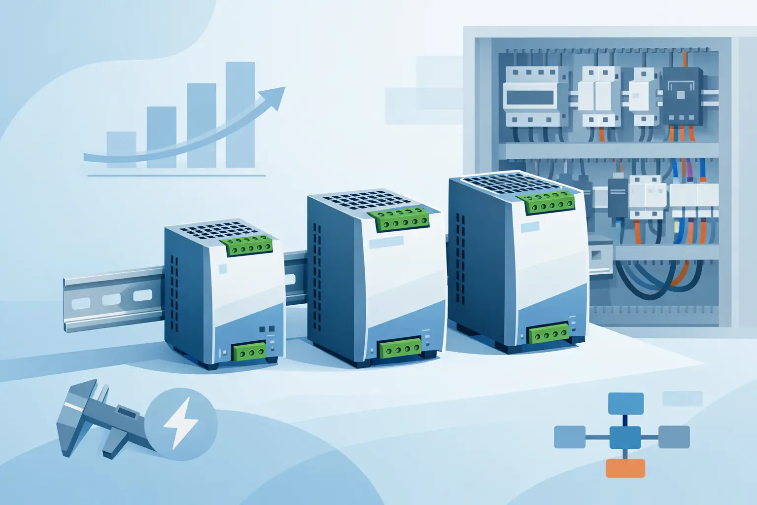
A 24 VDC supply that appears adequate on a schematic can still cause nuisance resets, undervoltage faults, and intermittent sensor failures once the panel is operating. DIN rail power supply sizing is the process of matching the supply to the real continuous load, startup demand, panel environment, and future changes - not simply adding the nameplate current on a few devices.
For plant engineers, panel builders, and maintenance teams, the goal is straightforward: specify a supply that keeps the control voltage stable under normal operation and predictable under abnormal conditions. A correctly sized unit also makes replacement easier because its voltage, output current, protection behavior, and installation constraints are documented before a failure creates urgency.
Start With the Actual DC Load
Begin with every device connected to the power supply output. Use the manufacturer's published current draw at the intended operating voltage, rather than assuming that all devices consume the same current listed on a drawing. PLC CPUs, remote I/O, HMI panels, managed switches, photoelectric sensors, valve manifolds, safety relays, and interface modules all contribute to the total.
Create a load schedule that separates continuous demand from switched demand. Continuous demand includes components powered whenever the machine is enabled, such as controllers, communications equipment, and sensors. Switched demand includes solenoids, contactor coils, brakes, indicator stacks, and other loads that may energize only during a cycle.
A useful load schedule should identify at least these four items:
- Device tag or exact part number
- Nominal supply voltage and steady-state current
- Peak or inrush current, where published
- Whether the load is continuous, intermittent, or externally switched
Add the worst-case simultaneous current rather than the average current of a machine cycle. A packaging line may run safely at a low average load but demand far more current when multiple pneumatic valves, alarms, and communication devices energize at once. If the sequence prevents loads from operating simultaneously, that can be considered, but only when the interlock logic is fixed, documented, and unlikely to be bypassed during troubleshooting.
The basic calculation is:
Required output current = total continuous current + simultaneous intermittent current + design margin
For example, a panel has 2.8 A of PLC, I/O, sensors, and network equipment operating continuously. Its valve bank and pilot devices can add 3.1 A when commanded together. The calculated demand is 5.9 A. A 6 A supply is too close to the limit for most industrial applications. A 10 A unit provides practical operating headroom and allows for modest additions later.
DIN Rail Power Supply Sizing Requires Margin
A supply should not normally be selected to run continuously at its maximum rated output. Operating at the edge of the rating reduces flexibility and can expose marginal conditions that are not obvious during bench testing. Line-voltage variation, elevated enclosure temperature, cable losses, and component aging all affect the available voltage at the load.
A common planning range is 20% to 30% reserve capacity above the calculated worst-case steady operating load. The right margin depends on the application. A stable, mature panel with fixed loads may work well with 20%. A machine likely to receive additional sensors, remote I/O, or field options may justify 30% or more.
Margin is not a substitute for evaluating peaks. If a load needs 12 A for several hundred milliseconds and the supply can only provide 10 A with immediate current limiting, a 20% allowance based on steady-state current will not solve the problem. Check the data sheet for peak current capability, power boost function, overload mode, and the duration each feature supports.
Account for Inrush and Capacitive Loads
Many electronic devices draw a short but high inrush current when energized. HMI panels, industrial Ethernet switches, remote I/O stations, LED lighting circuits, DC-DC converters, and loads with large input capacitors can all create a startup demand that exceeds their normal operating current.
Power supplies respond to overload differently. Some enter constant-current limiting, some use foldback protection, some provide a timed boost, and some shut down and retry. The preferred behavior depends on the load. A supply that hiccups may protect itself effectively, but it can prevent a capacitive load from charging or cause repeated controller restarts. For a control system, review the trip curve and overload behavior as carefully as the amp rating.
Inductive DC loads require separate attention. Solenoids and relay coils can create voltage transients when switched off. Use appropriate suppression at the load, such as a diode, TVS device, or manufacturer-approved suppression module, based on the release-time requirement. Suppression protects output devices and helps prevent electrical noise from appearing as a power supply problem.
Check Derating Before Selecting the Amp Rating
The current rating on a DIN rail supply applies only within the manufacturer’s specified conditions. Ambient temperature, mounting orientation, clearance, input voltage range, altitude, and enclosure ventilation can reduce usable output power.
Heat is the most frequent sizing oversight. A 10 A, 24 VDC supply provides 240 W at its rated condition, but its available output may be lower inside a crowded enclosure at 122°F. When the same panel is installed near a press, oven, compressor room, or poorly ventilated machine base, the effective operating temperature can be much higher than the room temperature recorded during design.
Review the derating curve for the intended installation. If the required load intersects a derated region, move to a higher-capacity supply, improve panel cooling, or reduce heat sources around the power supply. Do not assume that a larger supply automatically fixes the issue if airflow and mounting clearances remain inadequate.
Input conditions matter as well. Confirm whether the unit will operate from 120 VAC, 230 VAC, 480 VAC with an appropriate converter, or a wide-range AC input. For DC-fed systems, verify the permitted input range and transient tolerance. A supply selected for a nominal voltage but exposed to poor incoming power can create faults that look like a downstream controls issue.
Size Distribution and Protection With the Supply
The power supply is only one part of the 24 VDC system. Output conductors, branch protection, electronic circuit protectors, terminal blocks, and load grouping determine whether one fault takes down the full panel.
Calculate voltage drop for long field runs, especially where sensors, valve terminals, and remote I/O are located far from the enclosure. A nominal 24 VDC output may be acceptable at the supply but insufficient at a load after cable resistance and shared return currents are considered. Increasing conductor size, shortening runs, or using local distribution can be more effective than increasing supply capacity.
Branch protection should coordinate with the supply's available short-circuit current. A conventional fuse or miniature circuit breaker may not clear quickly if the supply limits output current aggressively. Electronic circuit protection modules are often useful for separating PLC, communications, field I/O, and actuator branches, particularly when maintaining controller power during a field short is a priority.
For critical applications, consider redundancy instead of simply oversizing one unit. Two properly matched supplies with a redundancy module can improve continuity for a control voltage that cannot tolerate a single supply failure. Redundancy adds cost, panel space, heat, and maintenance requirements, so it is most appropriate where the cost of an unplanned stop justifies it.
Select for the Replacement and Service Reality
A technically correct supply still needs to fit the panel and procurement process. Confirm output voltage adjustment range, available DIN rail width, depth, terminal orientation, wiring method, approvals, and required accessories. If a replacement must match an existing design, compare protection behavior and connection layout as well as voltage and current.
Document the calculated load, ambient assumptions, selected margin, and approved replacement part numbers in the panel file. This gives maintenance personnel a defensible basis for replacement when the original unit is discontinued or a failure occurs outside normal purchasing hours. For cross-brand sourcing, American Automation 24 can help buyers identify industrial control components by exact model number and required specifications.
Before placing an order, verify the load schedule against the latest device data sheets and the supply derating curve for the actual enclosure conditions. That short review is often what separates a power supply that merely turns on from one that supports stable production for years.